To the next century
8 March 2019Alex Conacher visits the Elan Valley Aqueduct project in Wales, where tunnellers are constructing three bypass sections adjacent to the existing Victorian asset
Driving to the elan valley in mid Wales you pass reservoirs, hills, inquisitive sheep and mountains of waste slate left over from the days of heavy mining activity in the region. These are interspersed with a few villages and small towns, but not much else. It is beautiful and quiet.
It does have at least one vital infrastructural artery though: Elan Valley is the main source of water for Birmingham, the UK’s second city. With a metro population of four million (against London’s 14), it has a substantial thirst. This supply is currently delivered via a gravity aqueduct that opened in 1904. The structure varies depending upon the topography, but consists of mined tunnels, open-cut conduits and inverted syphon pipe work. The tunnel is an inverted U-shape, advanced primarily with a timber heading and lined with concrete filled behind a permanent brick formwork.
NEW WORKS/OVERVIEW
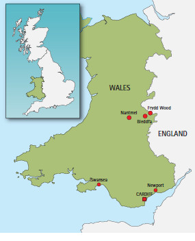
To ensure against deterioration of this critical asset, and after ruling out internal repairs, Severn Trent Water appointed specialist contractors Barhale and North Midland Construction (BNM Alliance) to conduct replacement works on a 4.5km length of tunnel. This consisted of replacing existing sections with a segmentally lined tunnel, located adjacent to the existing aqueduct. Each bypass would need to be connected during three separate three-day shutdowns, during which the aqueduct would be drained, and Birmingham would rely on reservoir capacity. The BNM Alliance’s solution had to be designed and built in such a way that the work could be terminated at any point if this three-day period elapsed. The tunnelling for the bypass work is split between three sites: Bleddfa (1.8km), Nantmel (1km) and Frydd Wood (1.8km), each having very different requirements.
GEOLOGY AND TBM SELECTION
The job is split into three separate tunnel drives of differing ground conditions, meaning it was necessary to match the machine to the job. For example, Frydd Wood, the final drive, was known to contain the hardest rock and so a 3.76m-diameter Herrenknecht mixed head EPBM was used, designed more towards rock than soil, but still capable of dealing with the clays and softer material in the profile.
Tooling was the same between all the drives, and TBM guidance was handled by a VMT gyroscope and water-level modified from a pipe jack system. The TBM drives were undertaken in order of how much was known about the geology, with the Frydd Wood guiding TBM design due to its rocky conditions:
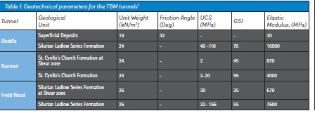
¦ The first drive, Bleddfa, is directly underlain by sequence of rocks of the Ludlow Series of the Silurian age comprising undifferentiated mudstones, siltstones and sandstone. In some sections the tunnel horizon passes through superficial deposits comprising of varying density.
¦ Borehole data from Nantmel indicated that there was a limited presence of superficial deposits underlain by the St. Cynllo’s Church Formation, which forms the solid geology in the area. The tunnel horizon passes through extremely to highly weathered rock.
¦ The Frydd Wood tunnel alignment is directly underlain by superficial deposits and Silurian Ludlow Series Formation, which is a similar type of geology as encountered in the Bleddfa tunnel alignment. Based on the investigation data provided, the tunnel alignment only passes through this Formation, with limited areas of highly weathered sections. Groundwater levels range from approximately 20m to a maximum of 40m above tunnel crown.1 Settlement was not a concern on the project, except perhaps at the connection locations, but these were all in hard rock. Despite the project running as little as 15m from a nearby hamlet and passing under the A488 just 8m at its shallowest, pre- and postcondition surveys revealed no impact.
In reality, says Ken MacGregor, project director for the BNM Alliance, the risk of a pressure blowout was greater than settlement, but this did not happen either: The PLC recorded pressures in real time. As a managing team, we reviewed the geology prior to the TBM drive and developed a route risk assessment based on this, which helped mitigate any risk.
Rapid procurement
The procurement process was shortened by a year with some reverse-engineering, which eliminated the need for detailed mechanical design by the manufacturer. An approximate finished diameter for the tunnel was known, because there is a set volume of water that the tunnel needs to be able to convey. The BNM Alliance was able to approach Herrenknecht to source a 3m-diameter machine capable of coping with similar ground conditions. The manufacturer had just completed one for a job in Panama that closely matched the necessary criteria.
The contractor then briefed its chosen segment supplier, FP McCann, to prepare moulds to fit the TBM, and procurement was complete, barring a few tweaks, within six months.
TBM PERFORMANCE
At the time of Tunnels and Tunnelling’s visit, the two softer drives were complete, and TBM performance had been fairly good, considering the drives were in the less suitable geology. The team expected that the most efficient tunnelling was still to come.
The issues were mainly at the Nantmel site, with the softest geology offering “no strength at all”, according to the BNM Alliance. The best advance rate was 14 rings of 1.2m length in 24 hours of tunnelling. At Bleddfa the contractor mainly encountered grey mudstone of 60-80MPa and achieved an advance 36m. The geology at Frydd Wood has a uniaxial compressive strength of 100- 120MPa.
This was working with a shift pattern of two 12-hour shifts per day, working five days per week.
As the wear has been good, changes to the main cutters have only been made between drives, despite several curves along the alignment, the tightest being a 250m radius. Gauge cutters, meanwhile, have lasted 350m in the 60-80MPa rock, having been recorded and changed often. The on-site teams maintain the head, including replacing the cutting discus, while cutter refurbishment is being carried out off-site, resulting in large savings according to MacGregor:
“A disc cutter costs GBP 2,800 [USD 3,560] a piece, but for us to recondition them is about GBP 670 [USD 850], which is a huge saving. As this is a smaller project, we do not have a maintenance contract with Herrenknecht, and so we have had to be strategic and plan for what could fail in advance. If we didn’t, it’s a nine-week stoppage, something our schedule could not afford.”
More major problems, in the case of a problem with the main bearing, were on the risk register, though these did not require a fixed plan as the project was split with six and nine-month gaps between them, allowing for the correction of more serious issues.
LINING THE MAIN TUNNELS
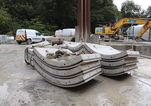
The tunnels were lined with concrete rings, each consisting of six trapezoidal segments supplied by FP McCann from a casting yard in Hinckley, Leicestershire. The segments are 1.2m long and 190mm thick, for a tunnel OD of 3.43m and an ID of 3.05m. Fibre reinforcement is standard, with 16-18 type steel reinforcement added in critical areas. This length is unusual for the UK, but this was a residual design feature from the Panama project mentioned previously. The TBM design was tweaked to take the rolling stock.
In terms of segment performance, no non-conformance reports were raised. Around some of the curves there was some slight spalling at knee level, which is caused as the TBM gantries pass through. Spalling at installation has been minimal and the contractor is pleased.
At Bleddfa the contractor had to perform repairs on approximately 1% of the rings, and even then it was mostly spall. Nantmel required even less; the segments were good quality and there have been no problems with the ringbuild. The segments and rings have been connected with bolts and fitted with Trelleborg Hinckel gaskets designed for 9 bars of water pressure. Beyond standard grouting, there is no other waterproofing needed, but because of the maximum depth of the tunnel (100m) and the lack of SI, the gaskets were designed to be certain of their effectiveness.
The tunnel also had to be designed for seismic activity. There are two fault lines running through the valleys that are being tunnelled, so this meant extra reinforcement for the segments in the connections and key sections of the tunnel.
CONDITION OF THE EXISTING AQUEDUCT
Considering the age of the original tunnels, the general condition of the asset was good. There was some cracking along the soffit at the Bleddfa site, which was repaired in the 1980s, but this had still shown signs of propagating. Additionally, various sections of the aqueduct are above ground, and although there have been no serious signs of deterioration yet, as a 100-year-old structure it would not be too many years before actual deterioration began to appear, so it was necessary to act to mitigate this. Getting rid of the above-ground elements of the aqueduct was one of the focuses of the scheme.
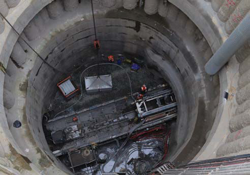
The first break into the existing conduit at Bleddfa took three hours with a 30-tonne machine to break a hole big enough to get in. According to MacGregor, the masonry was absolutely superb, and the contractor struggled even more with the pillars – the timber struts that they had in there. The side timbers were left concreted in and were perfectly preserved, so the team encountered green timber during their work.
CONNECTING STRUCTURES AND CONNECTION TO THE AQUEDUCT
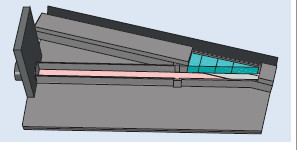
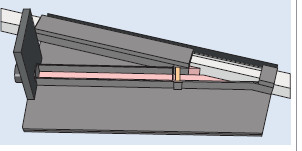
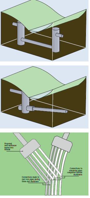
Some of the most challenging elements of the project came during the planned shut downs of the existing aqueduct; allowing the team to demolish sections of it. This enabled the team to construct a new transition structure in each pit, which is used to divert flows from the existing aqueduct into the newly constructed tunnel pipeline.
To protect the existing aqueduct during the tunnelling operations, the team had previously surrounded it in a temporary concrete wrapping structure. Once the aqueduct had been drained, the first stage of the works involved demolishing this layer of protection. A large section was cut out of the structure to expose the existing aqueduct below. The team then set to work breaking out and demolishing the existing brickwork and concrete with machine mounted breakers.
Prior to the demolition operations the team constructed a new transition structure, which tied into the concrete wrap. This concrete structure will channel flows from the upstream aqueduct into the newly constructed tunnel. Two sets of stop logs were installed at the end of the new transition structure to seal the structure from the tunnelling area.
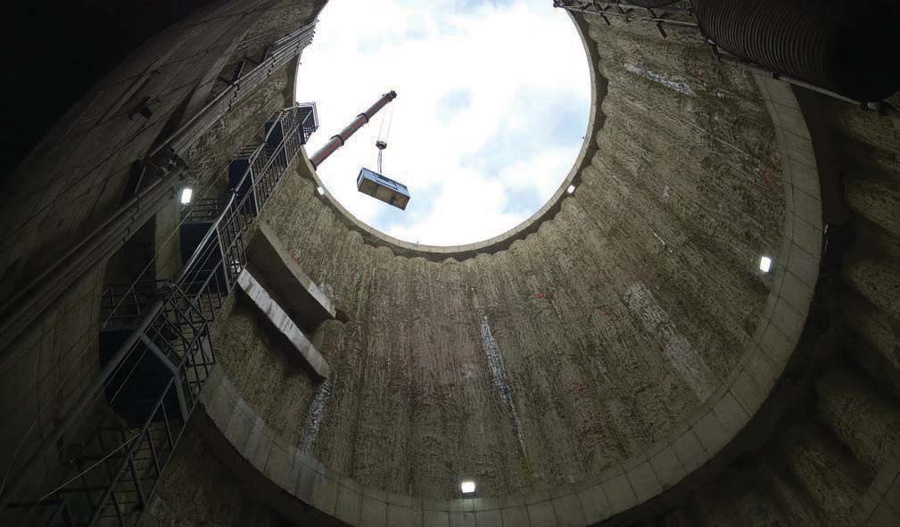
Finally, pre-cast concrete roof slab sections were lifted in place over the top of the structure to totally enclose the aqueduct before the flows were restored. On completion of the tunnelling the transition was extended the full length of the pit to tie into the new tunnel system.
The contractor was required to prepare an hour-by-hour programme for the shutdown works. There are plans, contingency plans, and back-ups for those. It was also necessary for the team to be able to abandon work and reconnect the water supply within eight hours, so the connection had to be designed in stages. Stoplogs were also needed to protect workers in case there were any problems holding back the flow.
WORKSITES
One of the most interesting parts of this job has been the site setup, as 60-65% of the overall work is temporary. The construction of the largest geotextile reinforced soil wall in Europe, supplied by Geosynthetics, is a particular highlight. This is an effective, environmentally friendly and economical approach to retaining a lot of material alongside the worksite, as is necessary in the Welsh valleys. There is not much material required from off-site, and there is no concrete to break out afterwards.
The method involves the use of a geotextile wrap (mesh and fabric) pressed against the excavated hill, backfilled, compacted, then build up the next layer over it. The largest one at the Elan Valley project, at Bleddfa, was around 135m long and 38m high. “Piling would probably be quicker to install,” adds MacGregor, “but this way you are not left with so much work at the end of the job.”
COMMUNITY AND ENVIRONMENT
While the people of Birmingham will doubtless be pleased to know that their water supply has been secured, one of the marks of a successful tunnel project is minimal disturbance. The Elan Valley project is lucky that it is in a remote area, so the usual problems of a dense urban environment are not an issue. However, the region is topographically awkward, and characterised by small villages and narrow, winding roads. For example, on the final site there was very little complaint raised about the removal of 80,000t of 120MPa rock from a hill near a town. As Tunnels and Tunnelling visited site, the contractor had been crushing rock for a week and operating dust suppression without being noticed.
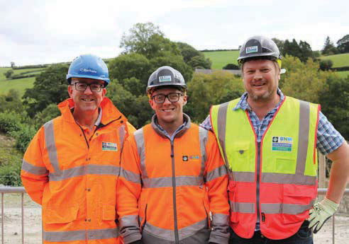
Before site setup the team engaged with the community about the site location and where they wanted the site road etc. They had worked closely with the local communities and said they found them to be extremely interested in what we are doing. “We try to accommodate site visits where we can, because often the local people are our biggest advocates,” says MacGregor. “We have 80-100 people working on site, of which 25% is local labour that we have employed and trained. We try to use local suppliers where possible, and we visit the local pubs of course.”
Muck removal
Muck is temporarily stored on site, but the project has worked closely with Natural Resource Wales to make use of spoil where possible, under the provisions of the U1 exemption certificates for the use of waste in construction.
This has also been helpful on the community relations. The undulating local landscape means a lot of the farmers and landowners in the area are looking for fill material to level out their properties, or to unlock more farmable land. “Natural Resource Wales has been very helpful, especially as the nearest landfill is 60 miles [100km] away and shipping the muck there would have cost us a fortune,” adds MacGregor.
APPROACHING COMPLETION
As the project wraps up, MacGregor reflects on the biggest challenges of each of the three drives:
¦ At Bleddfa it was the timescale. Severn Trent has outcome delivery incentive (ODI) penalties on each part of the project and the team was brought together from scratch, including all of the tunnel operatives and site crew.
¦ At Nantmel, the alignment was probably the trickiest element. It was quite a difficult launch into a tight curve, and because of this the contractor couldn’t get the advance rate that was hoped for.
¦ At Frydd Wood it is design. This section of the job was difficult, with the transition shaft, culvert, drop shaft, siphon, tunnel, well and siphon pipes. The teams are satisfied with the work undertaken to secure Birmingham’s water supply, and were pleasantly surprised by the quality of the tunnelling of their Victorian forebears. The new bypass tunnelling has been constructed for a 100-year design life.
“If 100 years from now someone has to break into our tunnel and they find it in a similar condition to the original aqueduct, they can consider us happy people,” concludes MacGregor.