Underground Maze
20 February 2020Paola De Pascali visited the Bank Station Capacity Upgrade (BSCU) site, which is placed in the City of London within historical buildings and Roman archaeological remains
Exploring the Bank Station Capacity Upgrade (BSCU) site is like stepping inside a labyrinth of tunnels, which are set to change into a new layout.
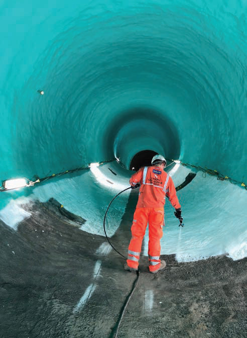
The journey starts from the disused King William Street Station (DKWS) where the original arched masonry walls are. The area has been sterilised as it was used for temporary accommodation and as a bomb shelter during World War 2. Walls have been painted, while lighting and ventilation have been added. John Comins, construction manager at Dragados explains that they use this area as access, workers hang their coats, and then they go to the welfare canteen to pick their stuff and go down. This is the daily route used by workers for a safe, quiet and clean pedestrian access.
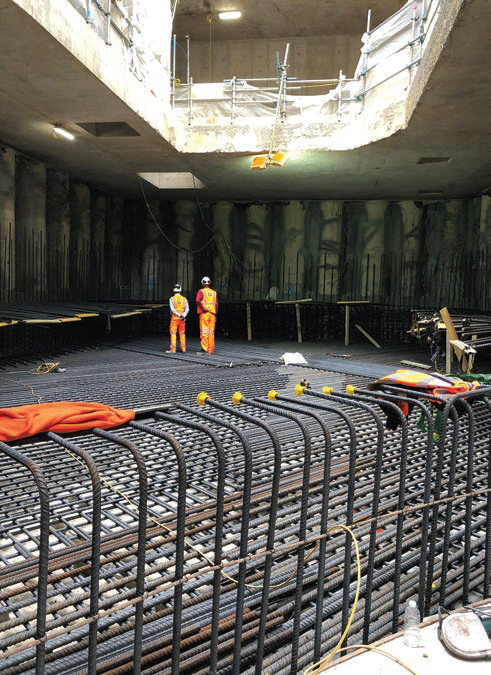
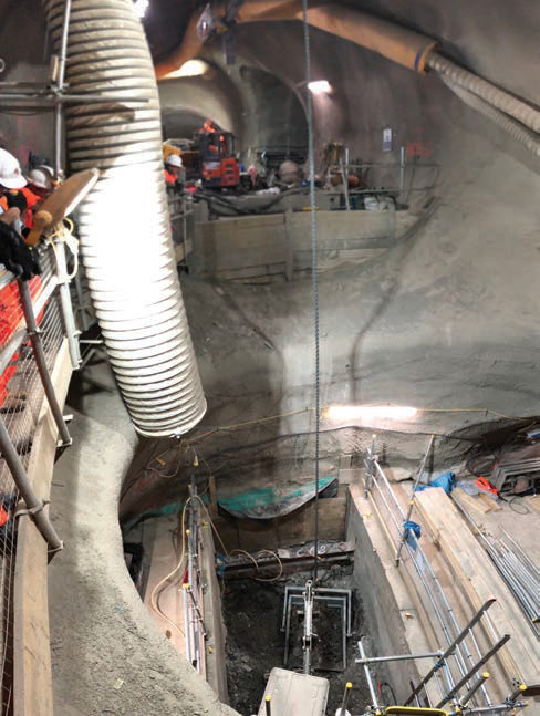
The transition area from the 4m-diameter, 520m-long running tunnel to the 9.5m diameter 135m-long platform tunnel is currently backfilled with clay to protect the invert and provide the temporary roadway for plant accessing the new tunnels.
Comins showed the step-free access from Cannon Street down to the DLR. “You stand at the Northern line level and the DLR is right beneath,” he says. “We constructed the shaft with SCL and there is the secant pile wall box structure above.
“We tunnelled over the top of the existing Northern Line (NL) southbound tunnel in three places then came down the two NL tunnels to form new cross passages between the tunnels without affecting train and passenger movement in the operating station. In one area this was all done by hand due to the limited headroom below the overlying sewer 2m above.”
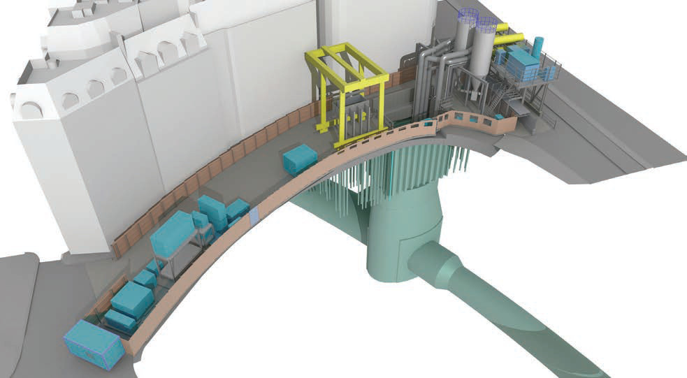
The project aims to split the Northern line as it currently runs through the Bank area and to place the south bound trains into a new 600m-long tunnel to the west of the existing station. The upgrade also includes a new interchange with extra passageways to improve passenger flow. There will also be new entry and exit points on Cannon Street as well as 12 new escalators, two new lifts and step-free access onto platforms. The BSCU will increase the capacity by 40 per cent by 2022, making journeys quicker and easier for its 120 million customers every year.
The cost of the project is GBP 600M (USD 772.9M). The client is Transport for London Underground, the contractor is Dragados UK. Dr. Sauer & Partners is the tunnel design consultant.
One of the key stakeholders is The Worshipful Company of Grocers who owns the building in Princes Court above one of the new tunnels. They are supported by their engineering adviser Arup.
Tunnelling works started in December 2016 approaching Princes Court in the summer of 2018. The southbound tunnel excavation, primary lining and the three-load transfer structures were completed in December 2018 without reaching the maximum building movement of 10mm and no building damage.
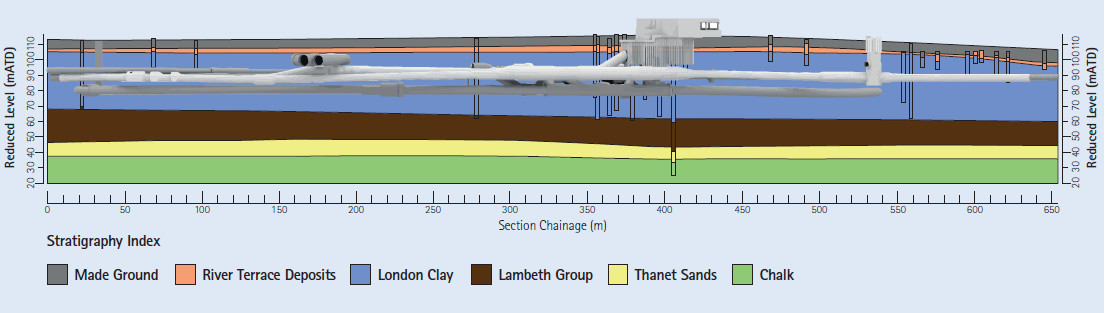
The new tunnels of the Bank Station Capacity Upgrade project primarily lie within London clay. The higher levels of the secant pile box to form the new Cannon Street entrance and the upper section of the temporary 40m-deep access shaft at Arthur Street were constructed in Made Ground and River Terrace Gravels.
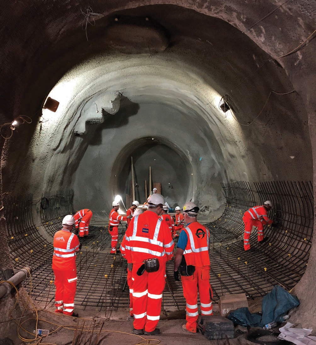
Due to the presence of pure clay, the natural geological features are limited. Approximately 94 per cent by excavated volume of the tunnels have been constructed by SCL and the remainder around and within the existing station infrastructure through square works hand tunnelling.
The shaft was sunk using SCL and a small Epiroc Oruga spraying robot on the shaft floor with concrete pumped from the surface by Suprema via a 101mm (4inch) steel delivery line fixed to the Arthur Street shaft wall. That was the full procedure to construct the shaft and the initial sections of tunnel comprising pit bottom, logistics chamber, muck bay and running tunnel. When approximately 100m of tunnel had been constructed, they introduced concrete remixer trucks to carry the concrete from pit bottom to the mobile Suprema pump behind the Oruga spraying robot at the advancing tunnel face.
The running tunnels have been excavated with an Schaeff ITC120 machine, which is a 25t tunnel excavator with a digging arm and a conveyor up in the middle.
“That was the right machine for the running tunnel profile and we achieved good productivity excavating and spraying in full face rounds,” says Comins. “After the pilot tunnel had been constructed through the upper middle of the new Northern Line platform tunnel profile we enlarged the tunnel using an Schaeff TE-210 excavator and sprayed the SCL primary lining using the Epiroc Potenza that were purchased in 2012 and used previously to construct the Stepney Green caverns of C305 Crossrail in 2013.”
The ITC120 has been used for excavating the running tunnel sections and the TE210 for the larger platform, interchange and Central Line moving walkway tunnels. A series of smaller conventional excavators were used to construct the smaller cross passages, temporary access tunnels and shafts to construct the new DLR adits.
Structural tunnel and shaft linings are designed to withstand all loads that will be experienced from construction to the end of their design life. The following loads and combination of loads were considered:
- Short term soil pressure
- Long term soil pressure
- Hydrostatic water pressure
- Concrete self-weight
- Surcharge load.
The tunnel structures consisting of primary and secondary linings have been analysed employing a threedimensional finite element analysis (3D FEA) that models all the major excavation sequences in a detailed manner.
The primary linings were constructed from Cemex dry-mix concrete stored in 100t silos situated at Arthur Street and at the Whole Block Site (WBS) adjacent to Abchurch Lane. The mix was manufactured at the Cemex Doveholes quarry plant in Derbyshire and comprises limestone, marine sand, Castle Ketton cement, TAM super plasticizer, microsilica and Propex steel fibres.
Both primary and secondary linings have a design life of 120 years and a CEM II A/D (6 per cent microsilica) is used in both linings concrete mixes. Depending on the tunnel location a sheet or sprayed waterproofing membrane is installed between the primary and secondary linings.
In terms of concrete behaviour, Comins says that the quality of the material provided has been good.
“We had issues during initial tunnelling when the steel delivery lines used to block in the shaft and tunnel,” he says. “The main problem was related to the limited mixing in the tubes below the silo draw points in Arthur Street. We found that the concrete needed additional mixing in the remixer trucks to improve its workability and pumpability.”
The plan was to extend the running tunnel to the platform tunnel and then set up the remixer filling station in the larger Logistics tunnel adjacent to the nightshift spoil storage muck bay.
Comins explains that when they started to remix the concrete in the tunnel they found that the plasticiser started to work properly, the concrete became better mixed and so they had fewer blockages. The use of remixers caused an increase in waste concrete during the spraying of each round due to the washing out and cleaning, but resulted in less waste overall. “We soon achieved a very uniform and consistent concrete quality resulting in good overall tunnelling performance,” Comins adds.
Preserving Buildings
To control the settlement induced by tunnelling, the volume loss has to be calculated. “Excavation is still on going and the scale and complexity of the project makes it difficult to determine at the moment, however for some areas that we have looked into it ranges from 1.2-1.5 per cent,” says Comins. “We have a team looking at any damage of surrounding buildings and other third party assets.”
Several contingency measures were in place and ready to go, if required, to reduce the risk. For example, on St Mary Abchurch they did some work on the bell tower over there. “We put some steel straps to secure the actual tower,” says Comins. “Timber was protecting the main building itself. Some monitoring is also ongoing on existing cracks.
“We took many measures to protect Mansion House for example we removed a stain glass window to protect the building against the impact of the works and benefitted from the mitigation measures already installed from the DLR extension. We also protected the stairs from the main hallway with steel supports and pins.”
Comins adds that they did a lot of work to protect buildings and they got material to add if they should need to. But the settlement hasn’t had any major impact so compensation grouting wasn’t required.
“It wasn’t part of the design because the access is too difficult,” says Comins. “I think it was the right approach not to do the compensation grouting in any way because it could have an effect on the buildings by trying to compensate and have a negative impact on the buildings.
“When we demolished the Whole Block Site, we had a small amount of heave before the tunnel created settlement.”
Works run very close to the vaults of the Bank of England although their exact location is secret. The new tunnel runs through the piles supporting the Grocers’ Princes Street building. “So it took four years to negotiate and to design a suitable mechanism to transfer the load from the building above around and not onto the tunnels beneath,” says Comins. “We used PVC and fibreboard to keep the two structures apart and we had to do a series of larger caverns in a horseshoe shape with reinforced concrete, and it went through the piles. And then the cavern has to transfer the load from the building above to the ground around the tunnel and we tunnelled through them then installed the secondary lining.”
Dragados developed a Specific Action Plan for Princes Court, situated opposite the Bank of England, with real time website monitoring to ensure transparency to all involved parties in terms of procedures and to be ready to take pre-agreed actions in case of unpredicted movement.
“We are doing real time monitoring on the London Bridge sewer to see whether it might be influenced by tunnelling underneath,” says Comins.
“Also monitoring pavements, roads and levelling, threedimensional movement of buildings, façades, roofs, and around substructures of the tunnels around the area, including the operational station at Bank-Monument.”
Fibre optics have been installed by Cambridge Centre for Smart Infrastructure and Construction (CSIC) on St Mary Abchurch. The strain sensors monitored the ground behaviour during tunnelling works in addition to pile interception, transfer structure installation and post construction.
Some building movements have been measured manually, using levelling studs installed at basement level above each pile.
External superstructure movement have been monitored through an automatic total station and prisms. Comins adds that underground surveyors are also doing 3D monitoring. “The ground is behaving pretty much as expected.”
Challenging Sections
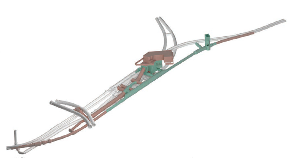
The initial upper part of the Arthur Street shaft was one of the most challenging pieces of work. Over a year it was needed to relocate the multitude of buried services to make way for the shaft and construct the piles to support the foundations for the gantry crane beams and dry-mix concrete storage silos. The available space around the top of the shaft and within the small narrow site compound to position the services such as ventilation, concrete supply, compressed air, workshop, water treatment, power supply to support the tunnelling works beneath was and still is severely restricted. The layout and establishment of the site and the installation of the temporary (tunnel services) gantry erected above King William Street next to the busy Monument junction required some careful planning and execution.
The first escalator to be constructed was ES2 at a 30° angle, which was driven from the WBS down into the Northern Line Cross Passage 3 whilst the secondary lining of the Persons of Restricted Mobility (PRM) shaft and the secant pile liner walls were being constructed from the WBS above.
Escalator 4 (ES4), which links the newly-lined Central Line (CL) Moving Walkway tunnel to the existing Westbound and Eastbound platform tunnels above, had to be driven upwards to avoid disrupting the existing busy operating underground station of Bank.
Comins explains, “This work was designed almost four years ago with a large element of early construction planning and was planned in detail through every step of the way by the SCL tunnelling team.
A large amount of enabling work was needed by the project’s Station team to prepare for the escalator drive through various existing station structures including the back filling of two SGI lined shafts that were constructed around 1895.
ES4 was excavated in 126 days. “We broke out through the sidewall of the temporary backfilled SCL tunnel at the end of the completed CL Moving Walkway tunnel with the TE210 machine and drove the first part of the escalator being the Lower Machine Chamber (LMC),” he says.
“A tricky piece of carefully controlled work was then needed to back mine over the temporary tunnel to form the junction of the LMC with the walkway tunnel. Only after this was completed could the main incline barrel be driven up to the existing CL platform tunnels in 24 days.
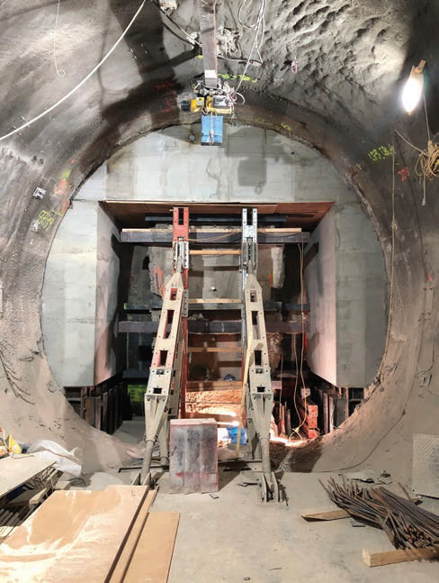
The transfer structure was also quite challenging. The existing unreinforced end-bearing piles of 6 to 8 Princes Street came down through the running tunnel profile.
“We had to break through these piles very carefully and there was a very detailed pre-agreed sequence of construction,” says Comins. “The method was fairly new and it was designed from scratch. We didn’t know how the building would react or what would happen if the piles would crack in tension.
“The idea was to tunnel through the piles and construct these load transfer structures around the tunnel in stages and we didn’t know what kind of effects could have on the building. The whole procedure went well, we didn’t have any cracks on the building. Everything went according to the plan.”
Hand Tunnelling
Hand tunnelling has been done in different areas, for example between two Northern Line tunnels.
“So we tunnelled down from the NL horizon using temporary SCL shafts in order to construct adits between the DLR tunnels. Some excavation had to be by hand through the existing backfilled structures,” says Comins. “We also tunnelled up and over the existing southbound Northern Line platform tunnel using the SCL method and down between and under them by hand using square works tunnelling techniques adopting the use of heavy steel beams and frames to support the SCL chamber above and grouted timber boards to temporarily support the clay faces.”
The percentage of works to be carried out by hand tunnelling is around 6 per cent.
The excavation tools used in hand tunnelling were generally conventional and traditional being the FL22 pneumatic jigger and clay spade and the German Hausher H11 concrete pick.
“We work with the Reactec wrist watches to monitor the vibration exposures from these hand-tunnelling tools and the data is downloaded and reviewed weekly,” says Comins.
“The series of design and constructability optimisation reviews reduced the manually intensive square works as much as possible. “Although we were expecting some hand works, we put together a detailed plan to manage the risk of handarm vibration. Part of that was the adoption of the Reactec monitoring system to capture the actual vibration exposure as accurately and practically as possible. We looked at tool selection, exposure time, weekly reviews, medical monitoring and training.”
Restrictions on Site
All works on site, particularly the surface works at the WBS, had to follow the Code of Construction Practice (CoCP) document that was agreed with the City of London Corporation and project.
Comins says, “During the demolition of the buildings within the WBS between Cannon Street and King William Street, the piling and subsequent civil works to construct the new station entrance, we generally worked a 10-hour day for five and a half days per week but not nightshift.”
In addition to the CoCP a minimum of four ‘quiet’ hours per day were required to avoid concrete breaking and drilling works.
Once the site had been established at Arthur Street and the top section of the temporary access shaft had been proved by excavating down to ensure all services were removed from the excavated profile down to 7m the shaft could then be constructed fully using steel sheet piles, frames and then the SCL method when in the clay below.
During the early proving shaft works, Roman archaeological remains were expected and were encountered. Three months of careful work by the Museum of London were required to catalogue and record the interesting findings dating back to the first century.
After this work the 10m-long sheet piles were pressed down into the clay using a Giken silent piler to create a rectangular opening of 5m x 9m that was subsequently reduced to 4.3m x 8m by the addition of the temporary steel propping frames at four levels.
The sequence of work was carefully planned to minimise the influence to the buildings above. As a precautionary measure a series of horizontal and vertical hydraulic jacks were used between the concrete piles and structural columns of the adjacent building to float the support and compensate for any localised differential settlement caused by the shaft sinking. We encountered no problems during sinking of the shaft from November 2016 to April 2017.
The spoil was stored underground and transported early morning from 5am until 3pm to minimise London traffic disruption. It was transported by Gordon tipper trucks and mainly reused for land reclamation in Essex.
The muck bay tunnel at pit bottom is the only spoil stockpile and has a capacity of approximately 630t.
“We were able to support the driving of three tunnel faces concurrently without becoming muck bound,” says Comins.
“During the day the spoil was coming straight down from the tunnel faces in 6t dumpers whilst the skid steer loaded the 18t Conquip Bulk-X bottom-discharging skip in 12 minutes. At peak we were loading out 35 trucks per day in this way.”
What was more subject to breakdown is the spraying equipment as it works in quite harsh conditions, noisy and dusty.
Comins explains that some spare parts of spraying equipment were the hardest things to replace because they are specialised machines, which might take six to seven weeks to be replaced.
“And also, hydraulic hoses can break because of concrete and abrasion,” he says. “But we didn’t lose too much time in break downs as we were well supported by good mechanical and electrical teams. We have had minor damages to some of the plant as it can be expected when tunnelling but nothing serious.”
Diesel Particulate Filters and fire suppression systems are fitted to all the tunnel plant including the Dieci remixers, dumpers, MEWPs, excavators and telehandlers. The ventilation system was designed around all available plant working concurrently.
The demolition material from the WBS was 98 per cent reused and recycled.
Talking about what could have been done in a different way in the whole project, Comins says: “I can’t think about something that I would change as the equipment selection, the labour, and the design were all good.”